Adopters Manual
The Samples
The quickest way to get started building with EDC is to work through
the samples. The samples cover everything from basic scenarios involving
sharing files to advanced streaming and large data use cases.
The MVD
The EDC Minimal Viable Dataspace (MVD) sets up and runs a
complete demonstration dataspace between two organizations. The MVD includes automated setup of a complete dataspace
environment in a few minutes.
Overview: Key Components
EDC is architected as modules called extensions that can be combined and customized to create components
that perform specific tasks. These components (the “C” in EDC) are not what is commonly referred to as "
microservices." Rather, EDC components may be deployed as separate services or collocated in a runtime process. This
section provides a quick overview of the key EDC components.
The Connector
The Connector is a pair of components that control data sharing and execute data transfer. These components are the
Control Plane and Data Plane, respectively. In keeping with EDC’s modular design philosophy, connector
components may be deployed in a single monolith (for simple use cases) or provisioned as clusters of individual
services. It is recommended to separate the Control Plane and Data Plane so they can be individually managed and scaled.

The Control Plane
The Control Plane is responsible for creating contract agreements that grant access to data, managing data transfers,
and monitoring usage policy compliance. For example, a data consumer’s control Plan initiates a contract negotiation
with a data provider’s connector. The negotiation is an asynchronous process that results in a contract agreement if
approved. The consumer connector then uses the contract agreement to initiate a data transfer with the provider
connector. A data transfer can be a one-shot (finite) transfer, such as a discrete set of data, or an ongoing (
non-finite) data stream. The provider control plane can pause, resume, or terminate transfers in response to certain
conditions. For example, if a contract agreement expires.
The Data Plane
The Data Plane is responsible for executing data transfers, which are managed by the Control Plane. A Data Plane sends
data using specialized technology such as a messaging system or data integration platform. EDC includes the Data Plane
Framework (DPF) for building custom Data Planes. Alternatively, a Data Plane can be built using other languages or
technologies and integrated with the EDC Control Plane by implementing
the Data Plane Signaling API.
Federated Catalog
The Federated Catalog (FC) is responsible for crawling and caching data catalogs from other participants. The FC builds
a local cache that can be queried or processed without resorting to complex distributed queries across multiple
participants.
Identity Hub
The Identity Hub securely stores and manages W3C Verifiable Credentials, including the presentation of VCs and the
issuance and re-issuance process.
The Big Picture: The Dataspace Context
EDC components are deployed to create a dataspace ecosystem. It is important to understand that there is no such thing
as “dataspace software.” At its most basic level, a dataspace is simply a context between two participants:

The Federated Catalog fetches data catalogs from other participants. A Connector negotiates a contract agreement
for data access between two participants and manages data transfers using a data plane technology. The Identity Hub
presents verifiable credentials that a participant connector uses to determine whether it trusts and should grant data
access to a counterparty.
The above EDC components can be deployed in a single runtime process (e.g., K8S ReplicaSet) or a distributed topology (
multiple ReplicaSets or clusters). The connector components can be further decomposed. For example, multiple control
plane components can be deployed within an organization in a federated manner where departments or subdivisions manage
specific instances termed Management Domains.
Customizing the EDC
EDC was designed with the philosophy that one size does not fit all. Before deploying an EDC-powered data sharing
ecosystem, you’ll need to build customizations and bundle them into one or more distributions. Specifically:
- Policies - Create a set of policies for data access and usage control. EDC adopts a code-first approach, which
involves writing policy functions.
- Verifiable Credentials - Define a set of W3C Verifiable Credentials for your use cases that your policy functions
can process. For example, a credential that identifies a particular partner type.
- Data transfer types - Define a set of data transfer technologies or types that must be supported. For example,
choose out-of-the-box support for HTTP, S3-based transfers, or Kafka. Alternatively, you can select your preferred
wire protocol and implement a custom data plane.
- Backend connectivity - You may need to integrate EDC components with back-office systems. This is done by writing
custom extensions.
Third parties and other open source projects distribute EDC extensions that can be included in a distribution. These
will typically be hosted on Maven Central.
1 - Dataspaces
A brief introduction to what a dataspace is and how it relates to EDC.
The concept of a dataspace is the starting point for learning about the EDC. A dataspace is a context between one or more participants that share data. A participant is typically an organization, but it could be any entity, such as a service or machine.
Dataspace Protocol (DSP): The Lingua Franca for Data Sharing
The messages exchanged in a dataspace are defined by the Dataspace Protocol Specification (DSP). EDC implements and builds on these asynchronous messaging patterns, so it will help to become acquainted with the specification. DSP defines how to retrieve data catalogs, conduct negotiations to create contract agreements that grant access to data, and send data over various lower-level wire protocols. While DSP focuses on the messaging layer for controlling data access, it does not specify how “trust” is established between participants. By trust, we mean on what basis a provider makes the decision to grant access to data, for example, by requiring the presentation of verifiable credentials issued by a third-party. This is specified by the Decentralized Claims Protocol (DCP), which layers on DSP. We won’t cover the two specifications here, other than to highlight a few key points that are essential to understanding how EDC works.
After reading this document, we recommend consulting the DSP and DCP specifications for further information.
The Question of Identity
One of the most important things to understand is how identities work in a dataspace and EDC. A participant has a single identity, which is a URI. EDC supports multiple identity systems, including OAuth2 and the Decentralized Claims Protocol (DCP). If DCP is used, the identity will be a Web DID.
An EDC component, such as a control plane, acts as a participant agent; in other words, it is a system that runs on behalf of a participant. Therefore, each component will use a single identity. This concept is important and nuanced. Let’s consider several scenarios.
Simple Scenarios
Single Deployment
An organization deploys a single-instance control plane. This is the simplest possible setup, although it is not very reliable or scalable. In this scenario, the connector has exactly one identity. Now take the case where an organization decides on a more robust deployment with multiple control plane instances hosted as a Kubernetes ReplicaSet. The control plane instances still share the same identity.
Distributed Deployment
EDC supports the concept of management domains, which are realms of control. If different departments want to manage EDC components independently, the organization can define management domains where those components are deployed. Each management domain can be hosted on distinct Kubernetes clusters and potentially run in different cloud environments. Externally, the organization’s EDC infrastructure appears as a unified whole, with a single top-level catalog containing multiple sub-catalogs and data sharing endpoints.
In this scenario, departments deploy their own control plane clusters. Again, each instance is configured with the same identity across all management domains.
Multiple Operating Units
In some dataspaces, a single legal entity may have multiple subdivisions operating independently. For example, a multinational may have autonomous operating units in different geographic regions with different data access rights. In this case, each operating unit is a dataspace participant with a distinct identity. EDC components deployed by each operating unit will be configured with different identities. From a dataspace perspective, each operating unit is a distinct entity.
Common Misconceptions
Data transfers are only about sending static files
Data can be in a variety of forms. While the EDC can share static files, it also supports open-ended transfers such as streaming and API access. For example, many EDC use cases involve providing automated access to event streams or API endpoints, including pausing or terminating access based on continual evaluation of data use policies.
Dataspace software has to be installed
There is no such thing as dataspace “software” or a dataspace “application.” A dataspace is a decentralized context. Participants deploy the EDC and communicate with other participant systems using DSP and DCP.
EDC adds a lot of overhead
EDC is designed as a lightweight, non-resource-intensive engine. EDC adds no overhead to data transmission since specialized wire protocols handle the latter. For example, EDC can be used to grant access to an API endpoint or data stream. Once access is obtained, the consumer can invoke the API directly or subscribe to a stream without requiring the request to be proxied through EDC components.
Cross-dataspace communication vs. interoperability
There is no such thing as cross-dataspace communication. All data sharing takes place within a dataspace. However, that does not mean there is no such thing as dataspace interoperability. Let’s unpack this.
Consider two dataspaces, DS-1 and DS-2. It’s possible for a participant P-A, a member of DS-1, to share data with P-B, a member of DS-2, under one of the following conditions:
- P-A is also a member of DS-2, or
- P-B is also a member of DS-1
P-A shares data with P-B in the context of DS-1 or DS-2. Data does not flow between DS-1 and DS-2. It’s possible for one EDC instance to operate within multiple dataspaces as long as its identity remains the same (if not, different EDC deployments will be needed).
Interoperability is different. Two dataspaces are interoperable if:
- They have compatible identity systems. For example, if both dataspaces use DCP and Web DIDs, or a form of OAuth2 with federation between the Identity Providers.
- They have a common set of verifiable credentials (or claims) and credential issuers.
- They have an agreed set of data sharing policies.
If these conditions are met, it is possible for a single connector deployment to participate in two dataspaces.
2 - Modules, Runtimes, and Components
An overview of the EDC modularity system.
EDC is built on a module system that contributes features as extensions to a runtime. Runtimes are assembled to create a
component such as a control plane, a data plane, or an identity hub. A component may be composed of a single runtime
or a set of clustered runtimes:

The EDC module system provides a great deal of flexibility as it allows you to easily add customizations and target
diverse deployment topologies from small-footprint single-instance components to highly reliable, multi-cluster setups.
The documentation and samples cover in detail how EDC extensions are implemented and configured. At this point, it’s
important to remember that extensions are combined into one or more runtimes, which are then assembled into components.
A Note on Identifiers
The EDC uses identifiers based on this architecture. There are three identifier types: participant IDs, component IDs,
and runtime IDs. A participant ID corresponds to the organization’s identifier in a dataspace. This will vary by dataspace
but is often a Web DID. All runtimes of all components operated by an organization - regardless of where they are deployed
- use the same participant ID.
A component ID is associated with a particular component, for example, a control plane or data plane deployment. If an
organization deploys two data planes across separate clusters, they will be configured with two distinct component IDs.
All runtimes within a component deployment will share the same component ID. Component IDs are permanent and survive runtime
restarts.
A runtime ID is unique to each runtime instance. Runtime IDs are ephemeral and do not survive restarts. EDC uses runtime IDs to acquire cluster locks and for tracing, among other things.
3 - Control Plane
Explains how data, policies, access control, and transfers are managed.
The control plane is responsible for assembling catalogs, creating contract agreements that grant access to data, managing data transfers, and monitoring usage policy compliance. Control plane operations are performed by interacting with the Management API. Consumer and provider control planes communicate using the Dataspace Protocol (DSP). This section provides an overview of how the control plane works and its key concepts.
The main control plane operations are depicted below:
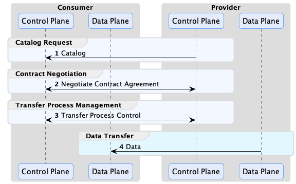
The consumer control plane requests catalogs containing data offers, which are then used to negotiate contract agreements. A contract agreement is an artifact that acts as a token granting access to a data set. It encodes a set of usage policies (as ODRL) and is bound to the consumer via its Participant ID. Every control plane must be configured with a Participant ID, which is the unique identifier of the dataspace participant operating it. The exact type of identifier is dataspace-specific but will often be a Web DID if the Decentralized Claims Protocol (DCP) is used as the identity system.
After obtaining a contract agreement, the consumer can initiate a data transfer. A data transfer controls the flow of data, but it does not send it. That task is performed by the consumer and provider data planes using a separate wire protocol. Data planes are typically specialized technology, such as a messaging system or data integration platform, deployed separately from the control plane. A control plane may use multiple data planes and communicate with them via a RESTful interface called the Data Plane Signaling API.
EDC is designed to handle all general forms of data. It’s important to note that a data transfer does not need to be file-based. It can be a stream, such as a market feed or an API that a client queries. Moreover, a data transfer does not need to be completed. It can exist indefinitely and be paused and resumed by the control plane at intervals. Now, let’s jump into the specifics of how the control plane works, starting briefly with the Management API and proceeding to catalogs.
Management API
The Management API is a RESTful interface for client applications to interact with the control plane. All client
operations described in this section use the Management API. We won’t cover the API in detail here since there is an
OpenAPI definition. The API can be secured using an authentication key or third-party OAuth2 identity provider, but it
is important to note that it should never be exposed over the Internet or other non-trusted networks.
The openapi documentation is available following this link:
https://eclipse-edc.github.io/Connector/openapi/management-api/
Catalogs, Datasets, and Offers
A data provider uses its control plane to publish a data catalog that other dataspace participants access. Catalog requests are made using DSP (HTTP POST). The control plane will return a response containing a DCAT Catalog The following is an example response with some sections omitted for brevity:
{
  "@context": {...},
  "dspace:participantId": "did:web:example.com",
  "@id": "567bf428-81d0-442b-bdc8-437ed46592c9",
  "@type": "dcat:Catalog",
  "dcat:dataset": [
    {
      "@id": "asset-1",
      "@type": "dcat:Dataset",
      "description": "...",
      "odrl:hasPolicy": {...},
      "dcat:distribution": [{...}]
    }
  ]
}
Catalogs contain Datasets, which represent data the provider wishes to make available to the requesting client. A Dataset has two important properties: odrl:hasPolicy, which is an ODRL usage policy, and one or more dcat:distribution entries that describe how to obtain the data. The catalog is serialized as JSON-LD. It is highly recommended that you become familiar with JSON-LD, and in particular, the JSON-LD Playground, since EDC makes heavy use of it.
Why does EDC use JSON-LD instead of plain JSON? There are two reasons. First, DSP is based on DCAT and ODRL, which rely on JSON-LD. As you will see, many EDC entities can be extended with custom attributes added by end-users. EDC needed a way to avoid property name clashes. JSON-LD provides the closest thing to a namespace feature for plain JSON.
Catalogs are not static documents. When a data consumer requests a catalog from a provider, the provider’s control plane dynamically generates a response based on the consumer’s identity and credentials. For example, a provider may offer specific datasets to a consumer or category of consumer (for example, if it is a tier-1 or tier-2 partner).
You will learn more about restricting access to datasets in the next section, but one way to do so is through the offer associated with a dataset. The following odrl:hasPolicy contains an Offer that specifies a dataset can only be used by an accredited manufacturer:
"odrl:hasPolicy": {
	"@id": "...",
	"@type": "odrl:Offer",
	"odrl:obligation": {
	  "odrl:action": {
		"@id": "use"
	  },
	  "odrl:constraint": {
		"odrl:leftOperand": {
		  "@id": "ManufacturerAccredidation"
		},
		"odrl:operator": {
		  "@id": "odrl:eq"
		},
		"odrl:rightOperand": "active"
	  }
	}
},
An offer defines usage policy. Usage policies are the requirements and permissions - or, more precisely, the duties, rights, and obligations - a provider imposes on a consumer to grant access to data. In the example above, the provider requires the consumer to be an accredited manufacturer. In practice, policies translate down into checks and verifications at runtime. When a consumer issues a catalog request, it will supply its identity (e.g., a Web DID) and potentially a set of Verifiable Presentations (VP). The provider control plane could check for a valid VP, or perform a back-office system lookup based on the client identity. Assuming the check passes, the dataset will be included in the catalog response.
A dataset will also be associated with one or more dcat:distributions:
"dcat:distribution": [
	{
		"@type": "dcat:Distribution",
		"dct:format": {
			"@id": "HttpData-PULL"
		},
		"dcat:accessService": {
		"@id": "a6c7f3a3-8340-41a7-8154-95c6b5585532",
		"@type": "dcat:DataService",
		"dcat:endpointDescription": "dspace:connector",
		"dcat:endpointUrl": "http://localhost:8192/api/dsp",
		"dct:terms": "dspace:connector",
		"dct:endpointUrl": "http://localhost:8192/api/dsp"
		}
	},
	{
		"@type": "dcat:Distribution",
		"dct:format": {
			"@id": "S3-PUSH"
		},
		"dcat:accessService": {
		"@id": "a6c7f3a3-8340-41a7-8154-95c6b5585532",
		"@type": "dcat:DataService",
		"dcat:endpointDescription": "dspace:connector",
		"dcat:endpointUrl": "http://localhost:8192/api/dsp",
		"dct:terms": "dspace:connector",
		"dct:endpointUrl": "http://localhost:8192/api/dsp"
		}
	}
]
A distribution describes the wire protocol a dataset is available over. In the above example, the dataset is available using HTTP Pull and S3 Push protocols (specified by the dct:format property). You will learn more about the differences between these protocols later. A distribution will be associated with a dcat:accessService, which is the endpoint where a contract granting access can be negotiated.
If you would like to understand the structure of DSP messages in more depth, we recommend looking at the JSON schemas and examples provided by the Dataspace Protocol Specification (DSP).
EDC Entities
So far, we have examined catalogs, datasets, and offers from the perspective of DSP messages. We will now shift focus to the primary EDC entities used to create them. EDC entities do not have a one-to-one correspondence with DSP concepts, and the reason for this will become apparent as we proceed.
Assets
An Asset is the primary building block for data sharing. An asset represents any data that can be shared. An asset is not limited to a single file or group of files. An asset could be a continual stream of data or an API endpoint. An asset does not even have to be physical data. It could be a set of computations performed at a later date. Assets are data descriptors loaded into EDC via its Management API (more on that later). Notice the emphasis on “descriptors”: assets are not the actual data to be shared but describe the data. The following excerpt shows an asset:
{
  "@context": {
    "edc": "https://w3id.org/edc/v0.0.1/ns/"
  },
  "@id": "899d1ad0-532a-47e8-2245-1aa3b2a4eac6",
  "properties": {
    "somePublicProp": "a very interesting value"
  },
  "privateProperties": {
    "secretKey": "..."
  },
  "dataAddress": {
    "type": "HttpData",
    "baseUrl": "http://localhost:8080/test"
  }
}
When a client requests a catalog, the control plane processes its asset entries to create datasets in a DSP catalog. An asset must have a globally unique ID. We strongly recommend using the JDK UUID implementation. Entries under the properties attribute will be used to populate dataset properties. The properties attribute is open-ended and can be used to add custom fields to datasets. Note that several well-known
properties are included in the edc namespace: id, description, version, name, contenttype (more on this in the next section on asset expansion).
In contrast, the privateProperties attribute contains properties that are not visible to clients (i.e., they will not be serialized in DSP messages). They can be used to internally tag and categorize assets. As you will see, tags are useful to select groups of assets in a query.
Why is the term Asset used and not Dataset? This is mostly for historical reasons since the EDC was originally designed before the writing of the DSP specification. However, it was decided to keep the two distinct since it provides a level of decoupling between the DSP and internal layers of EDC.
Remember that assets are just descriptors - they do not contain actual data. How does EDC know where the actual data is stored? The dataAddress object acts as a pointer to where the actual data resides. The DataAddress type is open-ended. It could point to an HTTP address (HttpDataAddress), S3 bucket (S3DataAddress), messaging topic, or some other form of storage. EDC supports a defined set of storage types. These can be extended to include support for virtually any custom storage. While data addresses can contain custom data, it’s important not to include secrets since data addresses are persisted. Instead, use a secure store for secrets and include a reference to it in the DataAddress.
Understanding Expanded Assets
The @context property on an asset indicates that it is a JSON-LD type. JSON-LD (more precisely, JSON-LD terms) is used by EDC to enable namespaces for custom properties. The following excerpt shows an asset with a custom property, dataFeed:
{
  "@context": {
    "edc": "https://w3id.org/edc/v0.0.1/ns/",
    "market-systems": "http://w3id.org/market-systems/v0.0.1/ns/"
  },
  "@id": "...",
  "properties": {
    "dataFeed": {
		"feedName": "Market Data",
		"feedType": "PRICING",
		"feedFrequency": "DAILY"
    }
  }
}
Notice a reference to the market-systems context has been added to @context in the above example. This context defines the terms dataFeed, feedName, feedType, and feedFrequency. When the asset is added to the control plane via the EDC’s Management API, it is expanded according to the JSON expansion algorithm This is essentially a process of inlining the full term URIs into the JSON structure. The resulting JSON will look like this:
{
"@id": "...",
"https://w3id.org/edc/v0.0.1/ns/properties": [
  {
	"http://w3id.org/market-systems/v0.0.1/ns/dataFeed": [
	  {
		"http://w3id.org/market-systems/v0.0.1/ns/feedName": [
		  {
			"@value": "Market Data"
		  }
		],
		"http://w3id.org/market-systems/v0.0.1/ns/feedType": [
		  {
			"@value": "PRICING"
		  }
		],
		"http://w3id.org/market-systems/v0.0.1/ns/feedFrequency": [
		  {
			"@value": "DAILY"
		  }
		]
	  }
	]
  }
]
}
Be careful when defining custom properties. If you forget to include a custom context and use simple property names (i.e., names that are not prefixed or a URI), they will be expanded using the EDC default context, https://w3id.org/edc/v0.0.1/ns/.
EDC persists the asset in expanded form. As will be shown later, queries for assets must reference property names in their expanded form.
Policies and Policy Definitions
Policies are a generic way of defining a set of duties, rights, or obligations. EDC and DSP express policies with ODRL. EDC uses policies for the following:
- As a dataset offer in a catalog to define the requirements to access data
- As a contract agreement that grants access to data
- To enable access control
Policies are loaded into EDC via the Management API using a policy definition, which contains an ODRL policy type:
{
  "@context": {
    "edc": "https://w3id.org/edc/v0.0.1/ns/"
  },
  "@type": "PolicyDefinition",
  "policy": {
    "@context": "http://www.w3.org/ns/odrl.jsonld",
    "@id": "8c2ff88a-74bf-41dd-9b35-9587a3b95adf",
    "duty": [
      {
        "target": "http://example.com/asset:12345",
        "action": "use",
        "constraint": {
          "leftOperand": "headquarter_location",
          "operator": "eq",
          "rightOperand": "EU"
        }
      }
    ]
  }
}
A policy definition allows the policy to be referenced by its @id when specifying the usage requirements for a set of assets or access control. Decoupling policies in this way allows for a great deal of flexibility. For example, specialists can create a set of corporate policies that are reused across an organization.
Contract Definitions
Contract definitions link assets and policies by declaring which policies apply to a set of assets. Contract definitions contain two types of policy:
- Contract policy
- Access policy
Contract policy determines what requirements a data consumer must fulfill and what rights it has for an asset. Contract policy corresponds directly to a dataset offer. In the previous example, a contract policy is used to require a consumer to be an accredited manufacturer. Access policy determines whether a data consumer can access an asset. For example, if a data consumer is a valid partner. The difference between contract and access policy is visibility: contract policy is communicated to a consumer via a dataset offer in a catalog, while access policy remains “hidden” and is only evaluated by the data provider’s runtime.
Now, let’s examine a contract definition:
{
  "@context": {
    "edc": "https://w3id.org/edc/v0.0.1/ns/"
  },
  "@type": "https://w3id.org/edc/v0.0.1/ns/ContractDefinition",
  "@id": "test-id",
  "edc:accessPolicyId": "access-policy-1234",
  "edc:contractPolicyId": "contract-policy-5678",
  "edc:assetsSelector": [
    {
      "@type": "https://w3id.org/edc/v0.0.1/ns/Criterion",
      "edc:operandLeft": "id",
      "edc:operator": "in",
      "edc:operandRight": ["id1", "id2", "id3"]
    },
    {
      "@type": "https://w3id.org/edc/v0.0.1/ns/Criterion",
      "edc:operandLeft": "productCategory",
      "edc:operator": "=",
      "edc:operandRight": "gold"
    },
  ]
}
The accessPolicyId and contractPolicyId properties refer to policy definitions. The assetsSelector property is a query (similar to a SQL SELECT statement) that returns a set of assets the contract definition applies to. This allows users to associate policies with specific assets or types of assets.
Since assetsSelectors are late-bound and evaluated at runtime, contract definitions can be created before assets exist. This is a particularly important feature since it allows data security to be put in place prior to loading a set of assets. It also enables existing policies to be applied to new assets.
Catalog Generation
We’re now in a position to understand how catalog generation in EDC works. When a data consumer requests a catalog from a provider, the latter will return a catalog result with datasets that the former can access. Catalogs are specific to the consumer and dynamically generated at runtime based on client credentials.
When a data consumer makes a catalog request via DSP, it will send an access token that provides access to the consumer’s verifiable credentials in the form of a verifiable presentation (VP). We won’t go into the mechanics of how the provider obtains a VP - that is covered by DCP and the EDC IdentityHub. When the provider receives the request, it generates a catalog containing datasets using the following steps:

The control plane first retrieves contract definitions and evaluates their access and contract policies against the consumer’s set of claims. These claims are populated from the consumer’s verifiable credentials and any additional data provided by custom EDC extensions. A custom EDC extension could look up claims such as partner tier in a back-office system. Next, the assetsSelector queries from each passing contract definition is then evaluated to return a list of assets. These assets are iterated, and a dataset is created by combining the asset with the contract policy specified by the contract definition. The datasets are then collected into a catalog and returned by the client. Note that a single asset may result in multiple datasets if more than one contract definition selects it.
Careful consideration needs to be taken when designing contract definitions, particularly the level of granularity at which they operate. When a catalog request is made, The access and contract policies of all contract definitions are evaluated, and the passing ones are selected. The asset selector queries are then run from the resulting set. To optimize catalog generation, contract definitions should select groups of assets rather than correspond in a 1:1 relationship with an asset. In other words, limit contract definitions to a reasonable number and use them as a mechanism to filter groups of assets. Adding custom asset properties that serve as selection labels is an easy way to do this.
Contract Negotiations
Once a consumer has received a catalog, it can request access to a dataset by sending a DSP contract negotiation request using the Management API. The contract negotiation takes the dataset offer as a parameter. When the request is received, the provider will respond with an acknowledgment. Contract negotiations are asynchronous, which means they are not completed immediately but sometime in the future. A contract negotiation progresses through a series of states defined by the DSP specification (which we will not cover). Both the consumer and provider can transition the negotiation. When a transition is attempted, the initiating control plane sends a DSP message to the counterparty.
If a negotiation is successfully completed (termed finalized), a DSP contract agreement message is sent to the consumer. The message contains a contract agreement that can be used to access data by opening a transfer process:
{
  "@context":  "https://w3id.org/dspace/2024/1/context.json",
  "@type": "dspace:ContractAgreementMessage",
  "dspace:providerPid": "urn:uuid:a343fcbf-99fc-4ce8-8e9b-148c97605aab",
  "dspace:consumerPid": "urn:uuid:32541fe6-c580-409e-85a8-8a9a32fbe833",
  "dspace:agreement": {
    "@id": "urn:uuid:e8dc8655-44c2-46ef-b701-4cffdc2faa44",
    "@type": "odrl:Agreement",
    "odrl:target": "urn:uuid:3dd1add4-4d2d-569e-d634-8394a8836d23",
    "dspace:timestamp": "2023-01-01T01:00:00Z",
    "odrl:permission": [{
      "odrl:action": "odrl:use" ,
      "odrl:constraint": [{
        "odrl:leftOperand": "odrl:dateTime",
        "odrl:operand": "odrl:lteq",
        "odrl:rightOperand": { "@value": "2023-12-31T06:00Z", "@type": "xsd:dateTime" }
      }]
    }]
  },
  "dspace:callbackAddress": "https://example.com/callback"
}
EDC implements DSP message exchanges using a reliable quality of service. That is, all message operations and state machine transitions are performed reliably in a transaction context. EDC will only commit a state machine transition if a message is successfully acknowledged by the counterparty. If a send operation fails, the associated transition will be rolled back, and the message will be resent. As with all reliable messaging systems, EDC operations are idempotent.
Working with Asynchronous Messaging and Events
DSP and EDC are based on asynchronous messaging, and it is important to understand that and design your systems appropriately. One anti-pattern is to try to “simplify” EDC by creating a synchronous API that wraps the underlying messaging and blocks clients until a contract negotiation is complete. Put simply, don’t do that, as it will result in complex, inefficient, and incorrect code that will break EDC’s reliability guarantees. The correct way to interact with EDC and the control plane is expressed in the following sequence diagram:
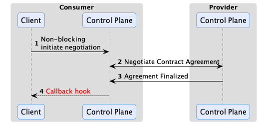
EDC has an eventing system that code can plug into and receive events when something happens via a callback hook. For example, a contract negotiation is finalized. The EventRouter is used by extension code to subscribe to events. Two dispatch modes are supported: asynchronous notification or synchronous transactional notification. The latter mode can be used to reliably deliver the event to an external destination such as a message queue, database, or remote endpoint. Integrations will often take advantage of this feature by dispatching contract negotiation finalized events to another system that initiates a data transfer.
Reliable Messaging
EDC implements reliable messaging for all interactions, so it is important to understand how this quality of service works. First, all messages have a unique ID and are idempotent. If a particular message is not acknowledged, it will be resent. Therefore, it is expected the receiving endpoint will perform de-duplication (which all EDC components do). Second, reliable messaging works across restarts. For example, if a runtime crashes before it can send a response, the response will be sent either by another instance (if running in a cluster) or by the runtime when it comes back online. Reliability is achieved by recording the state of all interactions using state machines to a transactional store such as Postgres. State transitions are initiated in the context of a transaction by sending a message to the counterparty, which is only committed after an acknowledgment is received.
Transfer Processes
After a Contract Negotiation has been finalized, a consumer can request data associated with an asset by initiating a Transfer Process via the Management API.
A finite transfer process completes after the data, such as a file, has been transferred. Other types of data transfers, such as a data stream or access to an API endpoint, may be ongoing. These types of transfer processes are termed non-finite because there is no specified completion point. They continue until they are explicitly terminated or canceled.

Pay careful attention to how data is modeled. In particular, model your assets in a way that minimizes the number of Contract Negotiations and Transfer Processes that need to be created. For large data sets such as machine-learning data, this is relatively straightforward: an asset can represent individual data set. Consumers will typically need to transfer the data once or infrequently, so the number of Contract Negotiations and Transfer Processes will remain small, typically one Contract Negotiation and a few transfers.
Now, let’s take as an example a supplier that wishes to expose parts data to their partners. Do not model each part as a separate asset, as that would require at least one contract negotiation and transfer process per part. If there are millions of parts, the number of contract negotiations and transfer processes will quickly grow out of control. Instead, having a single asset represents aggregate data, such as all parts, or a significant subset, such as a part type. Only one Contract Negotiation will be needed, and if the Transfer Process is non-finite and kept open, consumers can make multiple parts data requests (over the course of hours, days, months, etc.) without incurring additional overhead.
Flow Types
We’ll explain how to open a Transfer Process in the next section. First, it is important to understand the two modes for sending data from a provider to a consumer that EDC supports.
Consumer Pull
It requires the consumer to initiate the data flow operation. A common example of this is when a consumer makes an HTTP request to an endpoint and receives a response or pulls a message off a queue:
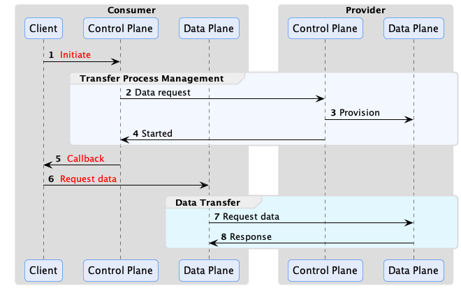
The EDR (Endpoint Data Reference) contains all the coordinates to reach the provider public endpoint where the data can be fetched. In the basic case, it is an HTTP endpoint, but it could be a message broker, an object storage and so on.
Provider Push
It requires the provider to actively push data to the consumer.
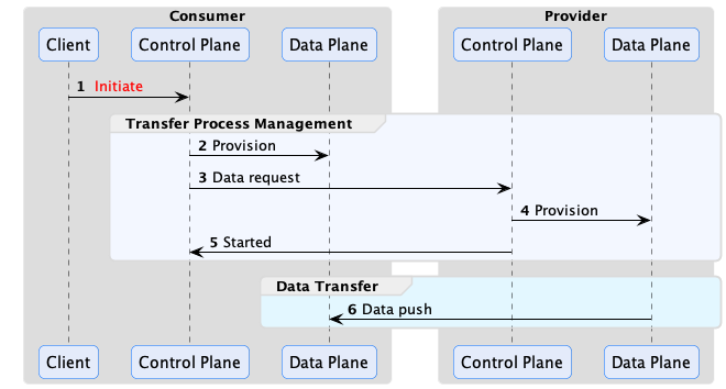
Note that, on the consumer side, the data plane role is to prepare the destination endpoint.
An example of provider push is when a consumer wishes to receive a dataset at an object storage endpoint that it controls.
Since the provider may need time to prepare the data, the consumer sends an access token when initiating a Transfer Process. The provider uses this token to push the data once it is ready.
Transfer Process States
Now that we have covered how transfer processes work at a high level, let’s look at the specifics. A transfer process is a shared state machine between the consumer and provider control planes. A transfer process will transition between states in response to a message received from the counterparty or as the result of a Management API operation. For example, a consumer will create a transfer process request via its Management API and send a request message to the provider. If the provider acknowledges the request with an OK, the transfer process state machine will be set to the REQUESTED state on both the consumer and provider. When the provider control plane is ready, it will send a message to the consumer, and the state machine will be transitioned to STARTED on both control planes.
The following are the most important transfer process states:
- REQUESTED - The consumer has requested a data transfer from the provider.
- STARTED - The consumer has received a start message from the provider. The data is available and can be pulled by the consumer or will be pushed by the provider.
- SUSPENDED - The consumer or provider has received a suspend message from the counterparty. All in-process data send operations will be paused.
- RESUMED - The consumer or provider has received a resume message from the counterparty. All in-process data send operations will be restarted.
- COMPLETED - The data transfer has been completed.
- TERMINATED - The consumer or provider has received a termination message from the counterparty. All in-process data send operations will be stopped.
There are a number of internal states that the consumer or provider can transition into without notifying the other party. The two most important are:
- PROVISIONED - When a data transfer request is made through the Management API on the consumer, its state machine will first transition to the PROVISIONED state to perform any required setup. After this is completed, the consumer control plane will dispatch a request to the provider and transition to the REQUESTED state. The state machine on the provider will transition to the PROVISIONED state after receiving a request and asynchronously completing any required data pre-processing.
- DEPROVISIONED - After a transfer has completed, the provider state machine will transition to the deprovisioned state to clean up any remaining resources.
As with the contract negotiation state machine, custom code can react to transition events using the EventRouter. There are also two further options for executing operations during the provisioning step on the consumer or provider. First, a Provisioner extension can be used to perform a task. EDC also includes the HttpProviderProvisioner, which invokes a configured HTTP endpoint when a provider control plane enters the provisioning step. The endpoint can front code that performs a task and asynchronously invoke a callback on the control plane when it is finished.
Policy Monitor
It may be desirable to conduct ongoing policy checks for non-finite transfer processes. Streaming data is a typical example where such checks may be needed. If a stream is active for a long duration (such as manufacturing data feed), the provider may want to check if the consumer is still a partner in good standing or has maintained an industry certification. The EDC PolicyMonitor can be embedded in the control plane or run in a standalone runtime to periodically check consumer credentials.
3.1 - Policy Engine
EDC includes a policy engine for evaluating policy expressions. It’s important to understand its design center, which
takes a code-first approach. Unlike other policy engines that use a declarative language, the EDC policy engine executes
code that is contributed as extensions called policy functions. If you are familiar with compiler design and visitors,
you will quickly understand how the policy engine works. Internally, policy expressed as ODRL is deserialized into a
POJO-based object tree (similar to an AST) and walked by the policy engine.
Let’s take one of the previous policy examples:
{
  "@context": {
    "edc": "https://w3id.org/edc/v0.0.1/ns/"
  },
  "@type": "PolicyDefinition",
  "policy": {
    "@context": "http://www.w3.org/ns/odrl.jsonld",
    "@id": "8c2ff88a-74bf-41dd-9b35-9587a3b95adf",
    "duty": [
      {
        "target": "http://example.com/asset:12345",
        "action": "use",
        "constraint": {
          "leftOperand": "headquarter_location",
          "operator": "eq",
          "rightOperand": "EU"
        }
      }
    ]
  }
}
When the policy constraint is reached during evaluation, the policy engine will dispatch to a function registered under
the key header_location. Policy functions implement the AtomicConstraintRuleFunction interface:
@FunctionalInterface
public interface AtomicConstraintRuleFunction<R extends Rule, C extends PolicyContext> {

    /**
     * Performs the evaluation.
     *
     * @param operator the operation
     * @param rightValue the right-side expression for the constraint
     * @param rule the rule associated with the constraint
     * @param context the policy context
     */
    boolean evaluate(Operator operator, Object rightValue, R rule, C context);

}
A function that evaluates the previous policy will look like the following snippet:
public class TestPolicy implements AtomicConstraintRuleFunction<Duty, ParticipantAgentPolicyContext> {

    public static final String HEADQUARTERS = "headquarters";

    @Override
    public boolean evaluate(Operator operator, Object rightValue, Duty rule, ParticipantAgentPolicyContext context) {
        if (!(rightValue instanceof String headquarterLocation)) {
            context.reportProblem("Right-value expected to be String but was " + rightValue.getClass());
            return false;
        }

        var participantAgent = context.participantAgent();

        var claim = participantAgent.getClaims().get(HEADQUARTERS);
        if (claim == null) {
            return false;
        }
        // ... evaluate claim and if the headquarters are in the EU, return true
        return true;
    }
}
Note that PolicyContext has its own hierarchy, that’s tightly bound to the policy scope.
Policy Scopes and Bindings
In EDC, policy rules are bound to a specific context termed a scope. EDC defines numerous scopes, such as one for
contract negotiations and provisioning of resources. To understand how scopes work, consider the following case,
“to access data, a consumer must be a business partner in good standing”:
{
  "constraint": {
    "leftOperand": "BusinessPartner",
    "operator": "eq",
    "rightOperand": "active"
  }
}
In the above scenario, the provider EDC’s policy engine should verify a partner credential when a request is made to
initiate a contract negotiation. The business partner rule must be bound to the contract negotiation scope since
policy rules are only evaluated for each scope they are bound to. However, validating a business partner credential
may not be needed when data is provisioned if it has already been checked when starting a transfer process. To avoid an
unnecessary check, do not bind the business partner rule to the provision scope. This will result in the rule being
filtered and ignored during policy evaluation for that scope.
The relationship between scopes, rules, and functions is shown in the following diagram:

Rules are bound to scopes, and unbound rules are filtered when the policy engine evaluates a particular scope. Scopes
are bound to contexts, and functions are bound to rules for a particular scope/context. This means that separate
functions can be associated with the same rule in different scopes. Furthermore, both scopes and contexts are hierarchical
and denoted with a DOT notation. A rule bound to a parent context will be evaluated in child scopes.
Be careful when implementing policy functions, particularly those bound to the catalog request scope (request.catalog),
which may involve evaluating a large set of policies in the course of a synchronous request. Policy functions should be
efficient and avoid unnecessary remote communication. When a policy function makes a database call or invokes a
back-office system (e.g., for a security check), consider introducing a caching layer to improve performance if testing
indicates the function may be a bottleneck. This is less of a concern for policy scopes associated with asynchronous
requests where latency is generally not an issue.
In Force Policy
The InForce is an interoperable policy for specifying in force periods for contract agreements. An in force period can
be defined as a duration or a fixed date.
All dates must be expressed as UTC.
Duration
A duration is a period of time starting from an offset. EDC defines a simple expression language for specifying the
offset and duration in time units:
<offset> + <numeric value>ms|s|m|h|d
The following values are supported for <offset>:
| Value | Description |
|---|
| contractAgreement | The start of the contract agreement defined as the timestamp when the provider enters the AGREED state expressed in UTC epoch seconds |
The following values are supported for the time unit:
| Value | Description |
|---|
| ms | milliseconds |
| s | seconds |
| m | minutes |
| h | hours |
| d | days |
A duration is defined in a ContractDefinition using the following policy and left-hand
operands https://w3id.org/edc/v0.0.1/ns/inForceDate:
{
  "@context": {
    "cx": "https://w3id.org/cx/v0.8/",
    "@vocab": "http://www.w3.org/ns/odrl.jsonld"
  },
  "@type": "Offer",
  "@id": "a343fcbf-99fc-4ce8-8e9b-148c97605aab",
  "permission": [
    {
      "action": "use",
      "constraint": {
        "and": [
          {
            "leftOperand": "https://w3id.org/edc/v0.0.1/ns/inForceDate",
            "operator": "gt",
            "rightOperand": {
              "@value": "contractAgreement",
              "@type": "https://w3id.org/edc/v0.0.1/ns/inForceDate:dateExpression"
            }
          },
          {
            "leftOperand": "https://w3id.org/edc/v0.0.1/ns/inForceDate:inForceDate",
            "operator": "lt",
            "rightOperand": {
              "@value": "contractAgreement + 100d",
              "@type": "https://w3id.org/edc/v0.0.1/ns/inForceDate:dateExpression"
            }
          }
        ]
      }
    }
  ]
}
Fixed Date
Fixed dates may also be specified as follows using https://w3id.org/edc/v0.0.1/ns/inForceDate operands:
{
  "@context": {
    "edc": "https://w3id.org/edc/v0.0.1/ns/inForceDate",
    "@vocab": "http://www.w3.org/ns/odrl.jsonld"
  },
  "@type": "Offer",
  "@id": "a343fcbf-99fc-4ce8-8e9b-148c97605aab",
  "permission": [
    {
      "action": "use",
      "constraint": {
        "and": [
          {
            "leftOperand": "https://w3id.org/edc/v0.0.1/ns/inForceDate",
            "operator": "gt",
            "rightOperand": {
              "@value": "2023-01-01T00:00:01Z",
              "@type": "xsd:datetime"
            }
          },
          {
            "leftOperand": "https://w3id.org/edc/v0.0.1/ns/inForceDate",
            "operator": "lt",
            "rightOperand": {
              "@value": "2024-01-01T00:00:01Z",
              "@type": "xsd:datetime"
            }
          }
        ]
      }
    }
  ]
}
Although xsd:datatime supports specifying timezones, UTC should be used. It is an error to use an xsd:datetime
without specifying the timezone.
No Period
If no period is specified the contract agreement is interpreted as having an indefinite in force period and will remain
valid until its other constraints evaluate to false.
Not Before and Until
Not Before and Until semantics can be defined by specifying a single https://w3id.org/edc/v0.0.1/ns/inForceDate
fixed date constraint and an
appropriate operand. For example, the following policy
defines a contact is not in force before January 1, 2023:
{
 "@context": {
   "edc": "https://w3id.org/edc/v0.0.1/ns/",
   "@vocab": "http://www.w3.org/ns/odrl.jsonld"
 },
 "@type": "Offer",
 "@id": "a343fcbf-99fc-4ce8-8e9b-148c97605aab",
 "permission": [
   {
     "action": "use",
     "constraint": {
       "leftOperand": "edc:inForceDate",
       "operator": "gt",
       "rightOperand": {
         "@value": "2023-01-01T00:00:01Z",
         "@type": "xsd:datetime"
       }
     }
   }
 ]
}
Examples
Please note that the samples use the abbreviated prefix notation "edc:inForceDate" instead of the full namespace
"https://w3id.org/edc/v0.0.1/ns/inForceDate".
4 - Data Plane
Describes how the EDC integrates with off-the-shelf protocols such as HTTP, Kafka, cloud object storage, and other technologies to transfer data between parties.
A data plane is responsible for transmitting data using a wire protocol at the direction of the control plane. Data planes
can vary greatly, from a simple serverless function to a data streaming platform or an API that clients access. One
control plane may manage multiple data planes that specialize in the type of data sent or the wire protocol requested by
the data consumer. This section provides an overview of how data planes work and the role they play in a dataspace.
Separation of Concerns
Although a data plane can be collocated in the same process as a control plane, this is not a recommended setup. Typically,
a data plane component is deployed as a separate set of instances to an independent environment such as a Kubernetes cluster.
This allows the data plane to be operated and scaled independently from the control plane. At runtime, a data plane must
register with a control plane, which in turn directs the data plane using the Data Plane Signaling API. EDC does not
ship with an out-of-the-box data plane. Rather, it provides the Data Plane Framework (DPF), a platform for building
custom data planes. You can choose to start with the DPF or build your own data plane using your programming language
of choice. In either case, understanding the data plane registration process and Signaling API are the first steps.
Data Plane Registration
In the EDC model, control planes and data planes are dynamically associated. At startup, a data plane registers itself
with a control plane using its component ID. Registration is idempotent and persistent and made available to all
clustered control plane runtimes via persistent storage. After a data plane is registered, the control plane
periodically sends a heartbeat and culls the registration if the data plane is unavailable.
The data plane registration includes metadata about its capabilities, including:
- The supported wire protocols and supported transfer types. For example, “HTTP-based consumer pull” or “S3-based provider push”
- The supported data source types.
The control plane uses data plane metadata for two purposes. First, it is used to determine which data transfer types
are available for an asset when generating a catalog. Second, the metadata is used to select a data plane when a
transfer process is requested.
Data Plane Signaling
A control plane communicates with a data plane through a RESTful interface called the Data Plane Signaling API. Custom
data planes can be written that integrate with the EDC control plane by implementing the registration protocol and the
signaling API.
The Data Plane Signaling flow is shown below:
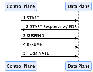
When a transfer process is started, and a data plane is selected, a start message will be sent. If the transfer process
is a consumer-pull type where data is accessed by the consumer, the response will contain an Endpoint Data Reference
(EDR) that contains the coordinates to the data and an access token if one is required. The control plane may send
additional signals, such as SUSPEND and RESUME, or TERMINATE, in response to events. For example, the control plane
policy monitor could send a SUSPEND or TERMINATE message if a policy violation is encountered.
The Data Plane Framework (DPF)
EDC includes a framework for building custom data planes called the DPF. DPF supports end-to-end streaming transfers
(i.e., data content is streamed rather than materialized in memory) for scalability and both pull- and push- style
transfers. The framework has extensibility points for supporting different data sources and sinks (e.g., S3, HTTP,
Kafka) and can perform direct streaming between different source and sink types.
The EDC samples contain examples of how to use and customize the DPF.
5 - Identity Hub
Identity Hub (IH) manages organization identity resources such as credentials for a dataspace participant. It is designed
for machine-to-machine interactions and does not manage personal verifiable credentials. Identity Hub implements the
Decentralized Claims Protocol (DCP) and is
based on key decentralized identity standards, including W3C DIDs, the
W3C did:web Method, and the
W3C Verifiable Credentials Data Model v1.1specifications, so we recommend
familiarizing yourself with those technologies first.
One question that frequently comes up is whether Identity Hub supports OpenID for Verifiable Credentials (OID4VC). The short answer is No. That’s because OID4VC mandates human (end-user) interactions, while Identity Hub is designed for machine-to-machine interactions where humans are not in the loop. Identity Hub is built on many of the same decentralized identity standards as OID4VC but implements DCP, a protocol specifically designed for non-human flows.
Identity Hub securely stores and manages W3C Verifiable Credentials, including handling presentation and issuance. But Identity Hub is more than an enterprise “wallet” since it handles key material and DID documents. Identity Hub manages the following identity resources:
- Verifiable Credentials. Receiving and managing issued credentials and generating Verifiable Presentations (VPs).
- Key Pairs. Generating, rotating, and revoking signing keys.
- DID Documents. Generating and publishing DID documents.
The EDC MVD Project provides a full test dataspace setup with Identity Hub. It’s an excellent tool to experiment with Identity Hub and decentralized identity technologies.
As we will see, Identity Hub can be deployed to diverse topologies, from embedded in a small footprint edge connector to an organization-wide clustered system. Before getting into these details, let’s review the role of Identity Hub.
Identities and Credentials in a Dataspace: The Role of Identity Hub
Note this section assumes a solid understanding of security protocols, DIDs, verifiable credentials, and modern cryptography concepts.
Identity Hub is built on the Decentralized Claims Protocol (DCP). This protocol overlays the Dataspace Protocol (DSP) by adding security and trust based on a decentralized identity model. To see how a decentralized identity system works, we will contrast it with a centralized approach.
Protocols such as traditional OAuth2 grants adopt a centralized model where a single identity provider or set of federated providers issue tokens on behalf of a party. Data consumers request a token from an identity provider, which, in turn, generates and signs one along with a set of claims. The data consumer passes the signed token to the data provider, which verifies the token using public key material from the identity provider:

The centralized model is problematic for many dataspaces:
- It is prone to network outages. If the identity provider goes down, the entire dataspace is rendered inoperable. Using federated providers only partially mitigates this risk while increasing complexity since large sections of a dataspace will still be subject to outage.
- It does not preserve privacy. Since an identity provider issues and verifies tokens, it is privy to communications between data consumers and providers. While the provider may not know the content of the communications, it is aware of who is communicating with whom.
- Participants are not in control of their identity and credentials. The identity provider creates identity tokens and manages credentials, not the actual dataspace participants.
Identity Hub and the Decentralized Claims Protocol are designed to address these limitations by introducing a model where there is no single point of failure, privacy is maintained, and dataspace participants control their identities and credentials. This approach is termed decentralized identity and builds on foundational standards from the W3C and Decentralized Identity Foundation.
The Presentation Flow
To understand the role of Identity Hub in a dataspace that uses a decentralized identity system, let’s start with a basic example. A consumer wants to access data from a provider that requires proof the consumer is certified by a third-party auditor. The certification proof is a W3C Verifiable Credential issued by the auditor. For now, we’ll assume the consumer’s Identity Hub already manages the VC (issuance will be described later).
When the consumer’s control plane makes a contract negotiation request to the provider, it must include a declaration of which participant it is associated with (the participant ID) and a way for the provider to access the required certification VC. From the provider’s perspective, it needs a mechanism to verify the consumer control plane is operating on behalf of the participant and that the VC is valid. Once this is done, the provider can trust the consumer control plane and grant it access to the data by issuing a contract agreement.
Instead of obtaining a token from a third-party identity provider, DCP mandates self-issued tokens. Self-issued tokens are generated and signed by the requesting party, which in the current example is the data consumer. As we will see, these self-issued tokens identify the data consumer and include a way for the provider to resolve the consumer’s credentials. This solves the issues of centralized identity systems highlighted above. By removing the central identity provider, DCP mitigates the risk of a network outage. Privacy is preserved since all communication is between the data consumer and the data provider. Finally, dataspace members remain in control of their identities and credentials.
Let’s look at how this works in practice. Identity and claims are transmitted as part of the transport header in DSP messages. The HTTP bindings for DSP do this using an Authorization token. DCP further specifies the header contents to be a self-signed JWT. The JWT sub claim contains the sender’s Web DID, and the JWT is signed with a public key contained in the associated DID document (as a verification method). The data provider verifies the sending control plane’s identity by resolving the DID document and checking the signed JWT against the public key.
This step only proves that the requesting control plane is operating on behalf of a participant. However, the control plane cannot yet be trusted since it must present the VC issued by the third-party auditor. DCP also specifies the JWT contains an access token in the token claim. The data provider uses the access token to query the data consumer’s Identity Hub for a Verifiable Presentation with one or more required credentials. It obtains the endpoint of the consumer’s Identity Hub from a service entry of type CredentialService in the resolved DID document. At that point, the provider connector can query the Identity Hub using the access token to obtain a Verifiable Presentation containing the required VC:
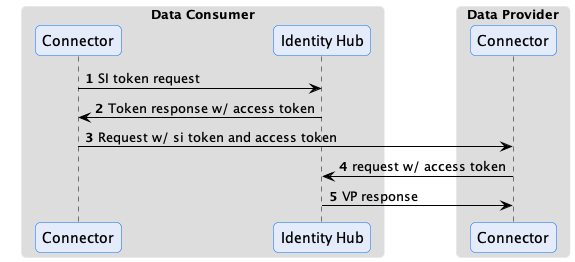
Once the VP is obtained, the provider can verify the VC to establish trust with the consumer control plane.
Why not just include the VP in the token or another HTTP header and avoid the call to Identity Hub? There’s a practical reason: VPs often exceed the header size limit imposed by HTTP infrastructure such as proxies. DSP and DCP could have devised the concept of a message envelope (remember WS-* and SOAP?) but chose not to because it ties credentials to outbound client requests. To see why this is limiting, consider the scenario where a consumer requests access to an ongoing data stream. The provider control plane may set up a policy monitor to periodically check the consumer’s credentials while the stream is active. In the DCP model, the policy monitor can query the consumer’s Identity Hub using the mechanism we described without the flow being initiated by the consumer.
Verifiable Presentation Generation
When the data provider issues a presentation request, the consumer Identity Hub generates a Verifiable Presentation based on the query received in the request. DSP defines two ways to specify a query: using a list of string-based scopes or a DIF Presentation Exchange presentation definition. Identity Hub does not yet support DIF Presentation Exchange (this feature is in development), so scopes are currently the only supported mechanism for requesting a set of credentials be included.
The default setup for Identity Hub translates a scope string to a Verifiable Credential type. For example, the following presentation query includes the AuditCertificationCredential:
{
  "@context": [
    "https://w3id.org/tractusx-trust/v0.8",
    "https://identity.foundation/presentation-exchange/submission/v1"
  ],
  "@type": "PresentationQueryMessage",
  "scope": ["AuditCertificationCredential"]
}
Identity Hub will process this as a request for the AuditCertificationCredential type. If the access token submitted along with the request permits the AuditCertificationCredential, Identity Hub will generate a Verifiable Presentation containing the AuditCertificationCredential. The generated VP will contain multiple credentials if more than one scope is present.
The default scope mapping behavior can be overridden by creating a custom extension that provides an implementation of the ScopeToCriterionTransformer interface.
Two VP formats are supported: JWT-based and Linked-Data Proof. The JWT-based format is the default and recommended format because, in testing, it exhibited an order of magnitude better performance than the Linked-Data Proof format. It’s possible to override the default JWT format by either implementing VerifiablePresentationService or providing a configuration of VerifiablePresentationServiceImpl.
When DIF Present Exchange is supported, client requests will be able to specify the presentation format to generate.
Issuance Flow
Note: Identity Hub issuance support is currently a work in progress.
W3C Verifiable Credentials enable a holder to present claims directly to another party without the involvement or knowledge of the credential issuer. This is essential to preserve privacy and mitigate against network outages in a dataspace. DCP defines the way Identity Hub obtains credentials from an issuer. In DCP, issuance is an asynchronous process. The Identity Hub sends a request to the issuer endpoint, including a self-signed identity token. Similar to the presentation flow described above, the identity token contains an access token the issuer can use to send the VC to the requester’s Identity Hub. This is done asynchronously. The VC could be issued immediately or after an approval process:
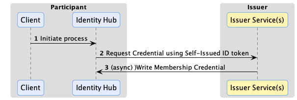
Issuance can use the same claims verification as the presentation flow. For example, the auditor issuer in the previous example may require the presentation of a dataspace membership credential issued by another organization. In this case, the issuer would use the access token sent in the outbound request to query for the required credential from the Identity Hub before issuing its VC.
Using the Identity Hub
Identity Hub is built using the EDC modularity and extensibility system. It relies on core EDC features, including
cryptographic primitives, Json-Ld processing, and DID resolution. This architecture affords a great deal of deployment flexibility. Let’s break down the different supported deployment scenarios.

Organizational Component
Many organizations prefer to manage identity resources centrally, as strict security and control can be enforced over these sensitive resources. Identity Hub can be deployed as a centrally managed component in an organization that other EDC components use. In this scenario, Identity Hub will manage all identity resources for an organization for all dataspaces it participates in. For example, If an organization is a member of two dataspaces, DS1 and DS2, that issue membership credentials, both credentials will be managed by the central deployment. Connectors deployed for DS1 and DS2 will use their respective membership credentials from the central Identity Hub.
Per Dataspace Component
Some organizations may prefer to manage their identity resources at the dataspace level. For example, a multinational may participate in multiple regional dataspaces. Each dataspace may be geographically restricted, requiring all data and resources to be regionally fenced. In this case, an Identity Hub can deployed for each regional dataspace, allowing for separate management and isolation.
Embedded
Identity Hub is designed to scale down for edge-style deployments where footprint and latency are primary concerns. In these scenarios, Identity Hub can be deployed embedded in the same runtime process as other connector components, providing a simple, fast, and efficient deployment unit.
Identity Hub APIs and Resources
Identity Hub supports two main APIs: the Identity API for managing resources and the DCP API, which implements the wire protocol defined by the Decentralized Claims Protocol Specification. End-users generally do not interact with the DCP API, so we won’t cover it here. The Identity API is the primary way operators and third-party applications interact with the Identity Hub. Since the API provides access to highly sensitive resources, it’s essential to secure it. Above all, the API should never be exposed over a public network such as the Internet.
The best way to understand the Identity API is to start with the resources it is designed to manage. This will give you a solid grounding for reviewing the OpenAPI documentation and using its RESTful interface. It’s also important to note that since the Identity Hub is extensible, additional resource types may be added by third parties to enable custom use cases.
The Participant Context
The Identity API includes CRUD operations for managing participant contexts. This API requires elevated administrative privileges.
A participant context is a unit of control for resources in Identity Hub. A participant context is tied to a dataspace participant identity. Most of the time, an organization will have a single identity and use the same Web DID in multiple dataspaces. Its Identity Hub, therefore, will be configured with exactly one participant context to manage identity and credential resources.
If an organization uses different identities in multiple dataspaces, its Identity Hub will contain one participant context per identity. All resources are contained and accessed through a participant context. The participant context acts as both a scope and security boundary. Access control for public client API endpoints is scoped to a specific participant context. For example, the JWT access token sent to data providers described above is associated with a specific context and may not be used to access resources in another context. Furthermore, the lifecycle of participant resources is bound to their containing context; if a participant context is removed, the operation will cascade to all contained resources.
A participant context can be in one of three states:
CREATED - The participant context is initialized but not operational. Resources may be added and updated, but they are not publicly accessible.ACTIVATED - The participant context is operational, and resources are publicly accessible.DEACTIVATED - The participant context is not operational. Resources may be added and updated, but they are not publicly accessible.
The participant context can transition from CREATED to ACTIVATED and between the ACTIVATED and DEACTIVATED states.
It’s useful to note that Identity Hub relies on the core EDC eventing system to enable custom extensions. Services may register to receive participant context events, for example, when a context is created or deleted, to implement custom workflows.
DID Documents
When a participant context is created, it is associated with a DID. After a participant context is activated, a corresponding DID document will be generated and published. Currently, Identity Hub only supports Web DIDs, so publishing the document will make it available at the URL specified by the DID. Identity Hub can support other DID methods through custom extensions.
In addition, custom publishers can be created by implementing the DidDocumentPublisher interface and adding it via an extension to the Identity Hub runtime. For example, a publisher could deploy Web DID documents to a web server. Identity Hub includes an extension for locally publishing Web DID documents. The extension serves Web DID documents using a public API registered under the /did path. Note that this extension is not designed to handle high-volume requests, as DID documents are served directly from storage and are not cached. For these scenarios, publishing to a web server is recommended.
Key Pair Resources
Key pair resources are used to sign and verify credentials, presentations, and other resources managed by Identity Hub. The public and private keys associated with a key pair resource can be generated by Identity Hub or provided when the resource is created. Identity Hub persists all private keys in a secure store and supports using Hashicorp Vault as the store.
A Key pair resource can be in one of the following states:
CREATEDACTIVATEDROTATEDREVOKED
Let’s walk through these lifecycle states.
Key Activation
When a key pair is created, it is not yet used to sign resources. When a key pair is activated, Identity Hub makes the public key material available as a verification method in the participant context’s DID document so that other parties can verify resources such as verifiable presentations signed by the private key. This is done by publishing an updated DID document for the participant context during the activation step.
Key Rotation
For security reasons, key pair resources should be periodically rotated and replaced by new ones. Identity Hub supports a staged rotation process to avoid service disruptions and ensure that existing signed resources can still be validated for a specified period.
For example, let’s assume private key A is used to sign Credential CA and public key A’ is used to verify CA. If the key pair A-A’ is immediately revoked, CA can no longer be validated, which may cause a service disruption. Key rotation can be used to avoid this. When the key pair A-A’ is rotated, a new key pair, B-B’, is created and used to sign resources. The private key A is immediately destroyed. A’, however, will remain as a verification method in the DID document associated with the participant context. CA validation will continue to work. When CA and all other resources signed by A expire, A’ can safely be removed from the DID document.
It’s important to perform key rotation periodically to enhance overall system security. This implies that signed resources should have a validity period less than the rotation period of the key used to sign them and should also be reissued on a frequent basis.
Key Revocation
If a private key is compromised, it must be immediately revoked. Revocation involves removing the verification method entry in the DID document and publishing the updated version. This will invalidate all resources signed with the revoked key pair.
Verifiable Credentials
Support for storing verifiable credentials using the DCP issuance flow is currently in development. In the meantime, adopters must develop custom extensions for storing verifiable credential resources or create them through the Identity API.
Resource Operations
Identity Hub implements transactional guarantees when resource operations are performed through the Identity API. The purpose of transactional behavior is to ensure the Identity Hub maintains a consistent state. This section catalogs those operations and guarantees.
Participant Context Operations
Create
When a participant context is created, the following sequence is performed:
- A transaction is opened.
- An API key is generated to access the context via the Identity API
- A DID document is created and added to storage.
- A default key pair is created and added to storage.
- The DID document is published if the participant context is set to active when created.
- The transaction commits on success, or a rollback is performed.
Delete
When a participant context is deleted, the following sequence is performed:
- A transaction is opened.
- The DID document is unpublished if the resource is in the
PUBLISHED state. - The DID document resource is removed from storage.
- All associated key pair resources are removed from storage except for private keys.
- The participant context is removed from storage.
- The transaction commits on success, or a rollback is performed.
- All private keys associated with the context are removed after the transaction is committed since Vaults are not transactional resources.
If destroying private keys fails, manual intervention will be required to clean them up. Note that the IH will be in a consistent state.
Activate
A participant context cannot be activated without a default key pair.
When a participant context is activated, the following sequence is performed:
- A transaction is opened.
- The context is updated in storage.
- The DID document is published.
- The transaction commits on success, or a rollback is performed.
Deactivate
When a participant context is deactivated, the following sequence is performed:
- A transaction is opened.
- The context is updated in storage.
- The DID document is unpublished.
- The transaction commits on success, or a rollback is performed.
There is a force option that will commit the transaction if the DID document unpublish operation is not successful.
Key Pair Operations
Activate
This operation can only be performed when the participant context is in the CREATED or ACTIVATED state.
When a key pair is activated, the following sequence is performed:
- A transaction is opened.
- The new key pair is added to storage.
- If the DID document resource is in the
PUBLISHED state, the DID document is published with all verification methods for public keys in the ACTIVATED state. - The transaction commits on success, or a rollback is performed.
If the transaction commit fails, the DID document must be manually repaired. This can be done by republishing the DID document.
Rotate
When a key pair is rotated and a new one is added, the following sequence is performed:
- A transaction is opened.
- The new key pair is added to storage.
- If the DID document resource is in the
PUBLISHED state, the DID document is published with a verification method for the new public key. - The transaction commits on success, or a rollback is performed.
- The old private key is destroyed (note, not the old public key) after the transaction is committed since Vaults are not transactional resources.
Revoke
When a key pair is rotated, the following sequence is performed:
When a key pair is revoked, the following sequence is performed:
- A transaction is opened.
- The key pair state is updated.
- If the DID document resource is in the
PUBLISHED state, the DID document is published with a verification method for the rotated public key removed. - The transaction commits on success, or a rollback is performed.
6 - Federated Catalog
Covers how publishing and retrieving federated data catalogs works.
TDB
7 - Distributions, Deployment, and Operations
Explains how to create distributions and design deployment architectures. This chapter also provides an overview of Management Domains and system configuration.
Using Bills-of-Material (BOMs)
In the Maven/Gradle world, bills-of-material are meta-modules with the sole purpose of declaring dependencies onto other modules. This greatly reduces the number of dependencies a developer needs to declare. By simply referencing the BOM module, all transitive dependencies are also referenced. The Eclipse Dataspace Components project declares several BOMs. The most important ones are listed here:
controlplane-base-bom: base BOM for an EDC control plane without an IdentityService implementation. Attempting to run this directly will result in an exceptioncontrolplane-dcp-bom: controlplane that uses DCP as identity systemdataplane-base-bom: runnable data plane image that contains HTTP transfer pipelines
FederatedCatalog:
federatedcatalog-base-bom: base BOM for FC modules. Does not contain any IdentityService implementationfederatedcatalog-dcp-bom: adds DCP to the FederatedCatalog base BOM
IdentityHub:
identityhub-base-bom: base BOM for IdentityHub. No DCP modules includedidentityhub-bom: default IdentityHub runtime image including DCP. Does not include/embed the SecureTokenService (STS).identityhub-with-sts-bom: IdentityHub runtime that has a SecureTokenService (STS) embedded.
In addition, most components also provide a *-feature-sql-bom BOM, which simply adds SQL persistence for all related entities, for example Assets, ContractDefinitions, etc. in the control plane BOM.
Using the Basic Template Repository to Create Distributions
The Modules, Runtimes, and Components chapter explained how EDC is built on a module system. Runtimes are assembled to create a component such as a control plane, a data plane, or an identity hub. EDC itself does not ship runtime distributions since it is the job of downstream projects to bundle features and capabilities that address the specific requirements of a dataspace or organization. However, EDC provides the Basic Template Repository to facilitate creating extensions and runtime distributions.
The EDC Basic Template Repository can be forked and used as a starting point for building an EDC distribution. You will need to be familiar with Maven Repositories and Gradle. Once the repository is forked, custom extensions can be added and included in a runtime. The template is configured to create two runtime Docker images: a control plane and data plane. These images are designed to be deployed as separate processes, such as two Kubernetes Replicasets.
EDC distributions can be created using other build systems if they support Maven dependencies since EDC modules are released to Maven Central. Using Gradle as the build system for your distribution has several advantages. One is that the distribution project can incorporate EDC Gradle Plugins such as the Autodoc and Build plugins to automate and remove boilerplate tasks.
Note: the template repository also leverages the BOM system.
Deployment Architectures and Operations
EDC does not dictate a specific deployment architecture. Components may be deployed to an edge device as a single low-footprint runtime or across multiple high-availability clusters. When deciding on an appropriate deployment architecture and operations setup, three considerations should be taken into account:
- How is your organization structured to manage data sharing?
- How should scaling be done?
- What components need to be highly available?
The answers to these questions will help define the required deployment architecture. We recommend starting with the simplest solution possible and only adding complexity when required. For example, a data plane must often be highly available and scalable, but a control plane does not. In this case, the deployment architecture should split the components and allocate different cluster resources to the data plane. We will now examine each question and how they impact deployment architectures.
Management Domains
The first question that needs to be assessed is: How is your organization structured to manage data sharing? In the simplest scenario, an organization may have a single IT department responsible for data sharing and dataspace membership company-wide. This is relatively easy to solve. EDC components can be deployed and managed by the same operations team. The deployment architecture will be influenced more by scaling and high-availability requirements.
Now, let’s look at a more complex case in which a multinational organization delegates data-sharing responsibilities to individual units. Each unit has its own IT department and data centers. In this setup, EDC components must be deployed and managed separately. This will impact control planes, data planes, and Identity Hubs. For example, the company could operate a central Identity Hub to manage organizational credentials and delegate control plane and data plane operations to the units. This requires a more complex deployment architecture where control and data planes may be hosted in separate environments, such as multiple cloud tenants.
To accommodate diverse deployment requirements, EDC supports management domains. A management domain is a realm of control over a set of EDC components. Management domains enable the operational responsibility of EDC components to be delegated throughout an organization. The following components may be included in a single management domain or spread across multiple domains:
- Catalog Server
- Control Plane
- Data Plane
- Identity Hub
To simplify things, we will focus on how a catalog server, control plane, and data plane can be deployed before discussing the Identity Hub. Management domains may be constructed to support the following deployment topologies.
Type 1: Single Management Domain
A single management domain deploys EDC components under one unified operations setup. In this topology, EDC components
can be deployed to a single, collocated process (management domains are represented by the black bounding box):

Type 1: One management domain controlling a single instance
More complex operational environments may deploy EDC components as separate clustered instances under the operational
control of a single management domain. For example, a Kubernetes cluster could be deployed with separate ReplicateSets
running pods of catalog servers, control planes, and data planes:

Type 1: One management domain controlling a cluster of individual ReplicaSets
Type 2: Distributed Management Domains
Single management domain topologies are not practical in organizations with independent subdivisions. Often, each subdivision is responsible for all or part of the data-sharing process. To accommodate these use cases, EDC components deployed to separate operational contexts (and hence separate management domains) must function together.
Consider the example of a large multinational conglomerate, Foo Industries, which supplies parts for widget production. Foo Industries has separate geographic divisions for production. Each division is responsible for sharing its supply chain data with Foo’s partners as part of the Widget-X Dataspace. Foo Industries participates under a single corporate identity in the dataspace, in this case using the Web DID did:web:widget-x.foo.com. Some partners may have access to only one of Foo’s divisions.
Foo Industries can support this scenario by adopting a distributed management domain topology. There are several different ways to distribute management domains.
Type 2A: DSP Catalog Referencing EDC Stacks
Let’s take the simplest to start: each division deploys an EDC component stack. Externally, Foo Industries presents a unified DSP Catalog obtained by resolving the catalog endpoint from Foo’s Web DID, did:web:widget-x.foo.com. The returned catalog will contain entries for the Foo Industries divisions a client can access (the mechanics of how this is done are explained below). Specifically, the component serving the DSP catalog would not be an EDC component, and thus not be subject to any management domains. To support this setup, Foo Industries could deploy the following management domains:

Type 2A: Distributed Management Domains containing an EDC stack
Here, two primary management domains contain a full EDC stack each. A root catalog (explained below) serves as the main entry point for client requests.
Type 2B: EDC Catalog Server and Control/Data Plane Runtimes
Foo Industries could also choose to deploy EDC components in separate management domains. For example, a central catalog server that runs in its own management domain and that fronts two other management domains consisting of control/data plane runtimes:

Type 2B: Distributed Management Domains containing a Catalog Server and separate Control/Data Plane runtimes
Type 2C: Catalog Server/Control Plane with Data Plane Runtime
Or, Foo Industries could elect to run a centralized catalog server/control plane:

Type 2C: Distributed Management Domains containing a Catalog Server/Control Plane and separate Data Plane runtimes
Identity Hub
The primary deployment scenario for Identity Hub is to run it as a central component under its own management domain. While Identity Hub instances could be distributed and included in the same management domains as a control/data plane pair, this would entail a much more complex setup, including credential, key, and DID document replication that is not supported out-of-the-box.
Setting Up Management Domains
Management domains are straightforward to configure as they mainly involve catalog setup. Recall how catalogs are structured as described in the chapter on [Control Plane concepts](Control Plane Concepts.md). Catalogs contain datasets, distributions, and data services. Distributions define the wire protocol used to transfer data and refer to a data service endpoint where a contract agreement can be negotiated to access the data. What was not mentioned is that a catalog is a dataset, which means catalogs can contain sub-catalogs. EDC takes advantage of this to implement management domains using linked catalogs. Here’s an example of a catalog with a linked sub-catalog:
{
  "@context": "https://w3id.org/dspace/v0.8/context.json",
  "@id": "urn:uuid:3afeadd8-ed2d-569e-d634-8394a8836d57",
  "@type": "dcat:Catalog",
  "dct:title": "Foo Industries Provider Root Catalog",
  "dct:description": [
    "A catalog of catalogs"
  ],
  "dcat:catalog": {
    "@type": "dcat:Catalog",
	"dct:description": [
	   "Foo Industries Sub-Catalog"
	],
    "dcat:distribution": {
      "@type": "dcat:Distribution",
      "dcat:accessService": "urn:uuid:4aa2dcc8-4d2d-569e-d634-8394a8834d77"
    },
    "dcat:service": [
      {
        "@id": "urn:uuid:4aa2dcc8-4d2d-569e-d634-8394a8834d77",
        "@type": "dcat:DataService",
        "dcat:endpointURL": "https://foo-industries.com/subcatalog"
      }
    ]
  }
}
In this case, the data service entry contains an endpointURL that resolves the contents of the sub-catalog. EDC deployments can consist of multiple sub-catalogs and nested sub-catalogs to reflect a desired management structure. For example, Foo Industries could include a sub-catalog for each division in its root catalog, where sub-catalogs are served from separate management domains. This setup would correspond to Type 2A shown above.
Configuring Linked Catalogs
Datasets are created from assets. The same is true for linked catalogs. Adding the following asset with the root catalog server’s Management API is the first step to creating a sub-catalog entry:
{
  "@context": {
    "@vocab": "https://w3id.org/edc/v0.0.1/ns/"
  },
  "@id": "subcatalog-id",
  "@type": "CatalogAsset",
  "properties": {...},
  "dataAddress": {
    "type": "HttpData",
    "baseUrl": "https://foo-industries.com/subcatalog"
  }
}
There are two things to note. First, the @type is set to CatalogAsset (which Json-Ld expands to https://w3id.org/edc/v0.0.1/ns/CatalogAsset). Second, the baseUrl of the data address is set to the sub-catalog’s publicly accessible URL.
The next step in creating a sub-catalog is to decide on access control, that is, which clients can see the sub-catalog. Recall that this is done with a contract definition. A contract definition can have an empty policy (“allow all”) or require specific credentials. It can also apply to (select) all sub-catalogs, sub-catalogs containing a specified property value, or a specific sub-catalog. The following contract definition applies an access policy and selects the previous sub-catalog:
{
  "@context": {
    "edc": "https://w3id.org/edc/v0.0.1/ns/"
  },
  "@type": "https://w3id.org/edc/v0.0.1/ns/ContractDefinition",
  "@id": "test-id",
  "edc:accessPolicyId": "access-policy-1234",
  "edc:contractPolicyId": "contract-policy-5678",
  "edc:assetsSelector": [
    {
      "@type": "https://w3id.org/edc/v0.0.1/ns/Criterion",
      "edc:operandLeft": "id",
      "edc:operator": "in",
      "edc:operandRight": ["subcatalog-id"]
    },
  ]
}
Alternatively, the following contract definition example selects a group of sub-catalogs in the “EU” region:
{
  "@context": {
    "edc": "https://w3id.org/edc/v0.0.1/ns/"
  },
  "@type": "https://w3id.org/edc/v0.0.1/ns/ContractDefinition",
  "@id": "test-id",
  "edc:accessPolicyId": "group-access-policy-1234",
  "edc:contractPolicyId": "contract-policy-5678",
  "edc:assetsSelector": [
    {
      "@type": "https://w3id.org/edc/v0.0.1/ns/Criterion",
      "edc:operandLeft": "region",
      "edc:operator": "=",
      "edc:operandRight": "EU"
    },
  ]
}
Once the catalog asset and a corresponding contract definition are loaded, a sub-catalog will be included in a catalog response for matching clients. Clients can then resolve the sub-catalogs by following the appropriate data service link.
Management Domain Considerations
If connector components are deployed to more than one management domain, it’s important to keep in mind that contract agreements, negotiations, and transfer processes will be isolated to a particular domain. In most cases, that is the desired behavior. If you need to track contract agreements across management domains, one way to do this is to build an EDC extension that replicates this information to a central store that can be queried. EDC’s eventing system can be used to implement a listener that receives contract and transfer process events and forwards the information to a target destination.
Component Scaling
Management domains help align a deployment architecture with an organization’s governance requirements for data sharing. Another factor that impacts deployment architecture is potential scalability bottlenecks. While measurements are always better than assumptions, the most likely potential bottleneck is moving data from a provider to a consumer, in other words, the data plane.
Two design considerations are important here. First, as explained in the chapter on [Control Plane concepts](Control Plane Concepts.md), do not model assets in a granular fashion. For example, if data consists of a series of small JSON objects, don’t model those as individual assets requiring separate contract negotiations and transfer processes. Instead, model the data as a single asset that can be requested using a single contract agreement through an API.
The second consideration entails how best to optimize data plane performance. In the previous example, the data plane will likely need to be much more performant than the control plane since the request rate will be significantly greater. This means that the data plane will also need to be scaled independently. Consequently, the data plane should be deployed separately from the control plane, for example, as a Kubernetes ReplicaSet running on a dedicated cluster.
Component High Availability
Another consideration that will impact deployment architecture is availability requirements. Consider this carefully. High availability is different from reliability. High availability measures uptime, while reliability measures correctness, i.e., did the system handle an operation in the expected manner? All EDC components are designed to be reliable. For example, remote messages are de-duplicated and handled transactionally.
High availability is instead a function of an organization’s requirements. A data plane must often be highly available, particularly if a shared data stream should not be subject to outages. However, a control plane may not need the same guarantees. For example, it may be acceptable for contract negotiations to be temporarily offline as long as data plane operations continue uninterrupted. It may be better to minimize costs by deploying a control plane to less robust infrastructure than a data plane. There is no hard-and-fast rule here, so you will need to decide on the approach that best addresses your organization’s requirements.
8 - Tuning
How to configure the EDC Runtime to reach out better performances
Out of the box the EDC provides a set of default configurations that aim to find a good balance for performances.
The extensibility nature of the EDC permits the user to configure it deeply.
We will explain how these settings can be fine tuned
State Machines
At the core of the EDC there is the State Machine
concept. In the most basic runtimes as Connector or IdentityHub there are some of them, and they can be configured
properly.
Settings
The most important settings for configuring a state machine are:
state-machine.iteration-wait- the time that the state machine will pass before fetching the next batch of entities to process in the case in the
last iteration there was no processing; Otherwise no wait is applied.
state-machine.batch-size- how many entities are fetched from the store for processing by the connector instance. The entities are locked
pessimistically against mutual access, so for the time of the processing no other connector instances can read
the same entities.
send.retry.limit- how many time a failing process execution can be tried before failure.
send.retry.base-delay.ms- how many milliseconds have to pass before the first retry after a failure. Next retries are calculated with an
exponential function (e.g. if the first delay is 10ms)
How to tune them
By default, on every iteration 20 entities (state-machine.batch-size) are fetched and leased by the runtime to be processed.
If no entity is processed in a whole iteration by default the state machine will wait for 1000 milliseconds (state-machine.batch-size)
until the next iteration.
If at least one entity is processed in an iteration, there’s no wait time before the next iteration.
So, for example reducing the state-machine.batch-size will mean that the state
machine will be more reactive, and increasing the state-machine.batch-size will mean that more entities will be processed
in the same iteration. Please note that increasing batch-size too much could bring to longer iteration time and that
reducing iteration-wait too much will make the iterations will be less efficient, as the fetch and lease (see, database interaction)
operation will happen more often.
If tweaking the settings doesn’t give you a performance boost, you can achieve them through horizontal scaling.
State machine nuances
How to tune them depends on the nature of the state machine, but let’s list the most important state machines and explain
what they do, this will help out in tune them appropriately.
The setting need to be constructed this way:
edc.<state machine name>.<setting>.
So, for example, edc.negotiation.provider.state-machine.batch-size configures the batch size for the negotiation provider
state machine.
Control-plane
negotiation.consumer: handles the contract negotiations from a consumer perspectivenegotiation.provider: handles the contract negotiations from a provider perspectivetransfer: handles the transfer processes
these state machines manages interactions with the counter-parties in the negotiation and transfer protocols. It’s good
practice to have them reactive to permit quick handshakes.
tuning suggestion:
state-machine.iteration-wait: in the order of 100/1000 milliseconds
state-machine.batch-size in the order of 10/100 \
policy.monitor: evaluates policies for ongoing transfers
this state machine ensures that the policies of ongoing transfers are still valid. It’s not necessary to have it run in
the order of milliseconds, given that in real world policies can last different days or months, so having some seconds but
also minutes as delay in evaluating them shouldn’t be an issue (if it is in your use case, please tune accordingly!)
tuning suggestion:
state-machine.iteration-wait: in the order of 30/60 minutes (translated in ms)
state-machine.batch-size in the order of 10/100 \
data.plane.selector: checks registered data planes availability
this state machine checks registered data planes and verifies if they are available or not. If the data-planes in your
environment are not supposed to change often the wait time can be keep high to avoid unnecessary database interaction:
tuning suggestion:
state-machine.iteration-wait: in the order of 1/10 minutes (translated in ms)
state-machine.batch-size in the order of 10/100 \
Data-plane
dataplane: handles the data flows
this state machine manages the data-flows so based on how many data flows are executed it can be tuned accordingly.
tuning suggestion:
state-machine.iteration-wait: in the order of 100/1000 milliseconds for many PUSH transfers, consider 1/10 seconds for few PULL transfers.
state-machine.batch-size in the order of 10/100 \
9 - Extensions
Details how to add customizations, features, and new capabilities to EDC components.
This chapter covers adding custom features and capabilities to an EDC runtime by creating extensions. Features can be wide-ranging, from a specific data validation or policy function to integration with an identity system. We will focus on common extension use cases, for example, implementing specific dataspace requirements. For more complex features and in-depth treatment, refer to the Contributor documentation.
This chapter requires a thorough knowledge of Java and modern build systems such as Gradle and Maven. As you read through this chapter, it will be helpful to consult the extensions contained in the EDC Samples repository.
The EDC Module System
EDC is built on a module system that contributes features as extensions to a runtime. It’s accurate to say that EDC, at its core, is just a module system. Runtimes are assembled to create components such as a control plane, a data plane, or an identity hub. The EDC module system provides a great deal of flexibility as it allows you to easily add customizations and target diverse deployment topologies, from small-footprint single-instance components to highly reliable, multi-cluster setups.
When designing an extension, it’s important to consider all the possible target deployment topologies. For example, features should typically scale up to work in a cluster and scale down to low-overhead and test environments. In addition to good architectural planning (e.g., using proper concurrency strategies in a cluster), we will cover techniques such as default services that facilitate support for diverse deployment environments.
To understand the EDC module system, we will start with three of its most important characteristics: static modules defined at build time, design-time encapsulation as opposed to runtime encapsulation, and a focus on extensions, not applications.
The EDC module system is based on a static design. Unlike dynamic systems such as OSGi, EDC modules are defined at build time and are not cycled at runtime. EDC’s static module system delegates the task of loading and unloading runtime images to deployment infrastructure, whether the JUnit platform or Kubernetes. A new runtime image must be deployed if a particular module needs to be loaded. In practice, this is easy to do, leverages the strengths of modern deployment infrastructure, and greatly reduces the module system’s complexity.
The EDC module system also does not support classloader isolation between modules like OSGi or the Java Platform Module System. While some use cases require strong runtime encapsulation, the EDC module system made the trade-off for simplicity. Instead, it relies on design-time encapsulation enforced by modern build systems such as Gradle or Maven, which support multi-project layouts that enforce class visibility constraints.
Finally, the EDC module system is not a framework like Spring. Its design is centered on managing and assembling extensions, not making applications easier to write by providing API abstractions and managing individual services and their dependencies.
Extension Basics
If you are unfamiliar with bundling EDC runtimes, please read the chapter on Distributions, Deployment, and Operations. Let’s assume we have already enabled a runtime build that packages all EDC classes into a single executable JAR deployed in a Docker container.
An EDC extension can be created by implementing the ServiceExtension interface:
public class SampleExtension implements ServiceExtension {

    @Override
    public void initialize(ServiceExtensionContext context) {
        // do something
    }
}
To load the extension, the SampleExtension must be on the runtime classpath (e.g., in the runtime JAR) and configured using a Java ServiceLoader provider file. The latter is done by including an entry for the implementation class in the META-INF/services/org.eclipse.edc.spi.system.ServiceExtension file.
SPI: Service Provider Interface
In the previous example, the extension did nothing. Generally, an extension provides a service to the runtime. It’s often the case that an extension also requires a service contributed by another extension. The EDC module system uses the Service Provider Interface (SPI) pattern to enable cross-extension dependencies:

An SPI module containing the shared service interface is created. The service implementation is packaged in a separate module that depends on the SPI module. The extension that requires the service then depends on the SPI module, not the implementation module. We will see in the next section how the EDC module system wires the service implementation to the extension that requires it. At this point, it is important to note that the build system maintains encapsulation since the two extension modules do not have a dependency relationship.
The SPI pattern is further used to define extension points. An extension point is an interface that can be implemented to provide a defined set of functionality. For example, there are extension points for persisting entities to a store and managing secrets in a vault. The EDC codebase is replete with SPI modules, which enables diverse runtimes to be assembled with just the required features, thereby limiting their footprint and startup overhead.
Providing and Injecting Services
The EDC module system assembles extensions into a runtime by wiring services to ServiceExtensions that require them and initialing the latter. An extension can provide services that are used by other extensions. This is done by annotating a factory method with the org.eclipse.edc.runtime.metamodel.annotation.Provider annotation:
public class SampleExtension implements ServiceExtension {

    @Provider
    public CustomService initializeService(ServiceExtensionContext context) {
       return new CustomServiceImpl();
    }
}
In the above example, initializeService will be invoked when the extension is loaded to supply the CustomService, which will be registered so other extensions can access it. The initializeService method takes a ServiceExtensionContext, which is optional (no-param methods can also be used with @Provider). Provider methods must also be public and not return void.
Provided services are singletons, so remember that they must be thread-safe.
The CustomService can be accessed by injecting it into a ServiceExtension using the org.eclipse.edc.runtime.metamodel.annotation.Inject annotation:
public class SampleExtension implements ServiceExtension {

	@Inject
	private CustomService customService;

    @Override
    public void initialize(ServiceExtensionContext context) {
        var extensionDelegate = ... // create and register a delegate with the CustomService
        customService.register(extensionDelegate);
    }
}
When the EDC module system starts, it scans all ServiceExtension implementations and builds a dependency graph from the provided and injected services. The graph is then sorted (topologically) to order extension startup based on dependencies. Each extension is instantiated, injected, and initialized in order.
The EDC module system does not support assigning extensions to runlevels by design. Instead, it automatically orders extensions based on their dependencies. If you find the need to control the startup order of extensions that do not have a dependency, reconsider your approach. It’s often a sign of a hidden coupling that should be explicitly declared.
Service Registries
Service Registries are often used in situations where multiple implementations are required. For example, entities may need to be validated by multiple rules that are contributed as services. The recommended way to handle this is to create a registry that accepts extension services and delegates to them when performing an operation. The following is an example of a registry used to validate DataAddresses:
public interface DataAddressValidatorRegistry {

    /**
     * Register a source DataAddress object validator for a specific DataAddress type
     *
     * @param type the DataAddress type string.
     * @param validator the validator to be executed.
     */
    void registerSourceValidator(String type, Validator<DataAddress> validator);

    /**
     * Register a destination DataAddress object validator for a specific DataAddress type
     *
     * @param type the DataAddress type string.
     * @param validator the validator to be executed.
     */
    void registerDestinationValidator(String type, Validator<DataAddress> validator);

    /**
     * Validate a source data address
     *
     * @param dataAddress the source data address.
     * @return the validation result.
     */
    ValidationResult validateSource(DataAddress dataAddress);

    /**
     * Validate a destination data address
     *
     * @param dataAddress the destination data address.
     * @return the validation result.
     */
    ValidationResult validateDestination(DataAddress dataAddress);
}
Validator instances can be registered by other extensions, which will then be dispatched to when one of the validation methods is called:
```java
public class SampleExtension implements ServiceExtension {

	@Inject private
	DataAddressValidatorRegistry registry;

    @Override
    public void initialize(ServiceExtensionContext context) {
        var validator = ... // create and register the validator
        customService.register(TYPE, validator);
    }
}
Configuration
Extensions will typically need to access configuration. The ServiceExtensionContext provides several methods for reading configuration data. Configuration values are resolved in the following order:
- From a
ConfigurationExtension contributed in the runtime. EDC includes a configuration extension that reads values from a file. - From environment variables, capitalized names are made lowercase, and underscores are converted to dot notation. For example, “HTTP_PORT” would be transformed to “HTTP.port.”
- From Java command line properties.
The recommended approach to reading configuration is through one of the two config methods: ServiceExtensionContext.getConfig() or ServiceExtensionContext.getConfig(path). The returned Config object can navigate a configuration hierarchy based on the dot notation used by keys. To understand how this works, let’s start with the following configuration values:
group.subgroup.key1=value1
group.subgroup.key2=value2
Invoking context.getConfig("group") will return a config object that can be used for typed access to group values or to navigate the hierarchy further:
var groupConfig = context.getConfig("group");
var groupValue1 = groupConfig.getString("subgroup.key1"); // equals "value1"
var subGroupValue1 = groupConfig.getConfig("subgroup").getString("key1"); // equals "value1"
The Config class contains other useful methods, so it is worth looking at it in detail.
Extension Loading
Service extensions have the following lifecycle that is managed by the EDC module system:
| Runtime Phase | Extension Phase | Description |
|---|
LOAD | | Resolves and introspects ServiceExtension implementations on the classpath, builds a dependency graph, and orders extensions. |
BOOT | | For each extension, cycle through the INJECT, INITIALIZE, and PROVIDE phases. |
| INJECT | Instantiate the service extension class and inject it with dependencies. |
| INITIALIZE | Invoke the ServiceExtension.initialize() method. |
| PROVIDE | Invoke all @Provider factory methods on the extension instance and register returned services. |
PREPARE | | For each extension, ServiceExtension.prepare() is invoked. |
START | | For each extension, ServiceExtension.start() is invoked. The runtime is in normal operating mode. |
SHUTDOWN | | For each extension in reverse order, ServiceExtension.shutdown() is invoked. |
Most extensions will implement the ServiceExtension.initialize() and ServiceExtension.shutdown() callbacks. | | |
Extension Services
Default Services
Sometimes, it is desirable to provide a default service if no other implementation is available. For example, in an integration test setup, a runtime may provide an in-memory store implementation when a persistent storage implementation is not configured. Default services alleviate the need to explicitly configure extensions since they are not created if an alternative exists. Creating a default service is straightforward - set the isDefault attribute on @Provider to true:
public class SampleExtension implements ServiceExtension {

    @Provider (isDefault = true)
    public CustomService initializeDefaultService(ServiceExtensionContext context) {
        new DefaultCustomService();
    }
}
If another extension implements CustomService, SampleExtension.initializeDefaultService() will not be invoked.
Creating Custom APIs and Controllers
Extensions may create custom APIs or ingress points with JAX-RS controllers. This is done by creating a web context
and registering JAX-RS resource under that context. A web context is a port and path mapping under which the controller
will be registered. For example, a context with a port and path set to 9191 and custom-api respectively may expose
a controller annotated with @PATH("custom-resources") at:
https:9191//localhost/custom-api/custom-resources
Web contexts enable deployments to segment where APIs are exposed. Operational infrastructure may restrict management
APIs to an internal network while another API may be available over the public internet.
EDC includes convenience classes for configuring a web context:
public class SampleExtension implements ServiceExtension {

    @Configuration
    private CustomApiConfiguration apiConfiguration;

    @Inject
    private WebServer webServer;

	@Inject
    private PortMappingRegistry portMappingRegistry;

    @Inject
    private WebService webService;

	public void initialize(ServiceExtensionContext context) {
        var portMapping = new PortMapping("custom-context", apiConfiguration.port(), apiConfiguration.path());
        portMappingRegistry.register(portMapping);

		webService.registerResource("custom-context", new CustomResourceController());
        webService.registerResource("custom-context", new CustomExceptionMapper());
	}

    @Settings
    record CustomApiConfiguration(
            @Setting(key = "web.http.custom-context.port", description = "Port for custom-context api context", defaultValue = 54321)
            int port,
            @Setting(key = "web.http.custom-context.path", description = "Path for custom-context api context", defaultValue = "/custom/path")
            String path
    ) {

    }
}
Let’s break down the above sample:
- The
PortMappingRegistry is responsible to keep track of all the different API contexts around the runtime - The
CustomApiConfiguration object takes care to parse the settings accordingly.
The default port and path can be overridden by configuration settings using the web.http.custom-context config key:
web.http.custom-context.path=/override-path
web.http.custom-context.port=9292
Once a web context is created, JAX-RS controllers, interceptors, and other resources can be registered with the
WebService under the web context alias. EDC uses Eclipse Jersey and supports
its standard features:
webService.registerResource("custom-context", new CustomResourceController());
webService.registerResource("custom-context", new CustomExceptionMapper());
Authentication
To enable custom authentication for a web context, you must:
- Implement
org.eclipse.edc.api.auth.spi.AuthenticationService and register an instance with the ApiAuthenticationRegistry. - Create an instance of the SPI class
org.eclipse.edc.api.auth.spi.AuthenticationRequestFilter and register it as a resource for the web context.
The following code shows how to do this:
public class SampleExtension implements ServiceExtension {

	@Inject
	private ApiAuthenticationRegistry authenticationRegistry;

	@Inject
	private WebService webService;

	@Override
	public void initialize(ServiceExtensionContext context) {
	    authenticationRegistry.register("custom-auth", new CustomAuthService());

	    var authenticationFilter = new AuthenticationRequestFilter(authenticationRegistry, "custom-auth");
	    webService.registerResource("custom-context", authenticationFilter);
	}
}
Events
The EDC eventing system is a powerful way to add capabilities to a runtime. All event types derive from org.eclipse.edc.spi.event.Event and cover a variety of create, update, and delete operations, including those for:
- Assets
- Policies
- Contract definitions
- Contract negotiations
- Transfer processes
To receive an event, register and EventSubscriber with the org.eclipse.edc.spi.event.EventRouter. Events can be received either synchronously or asynchronously. Synchronous listeners are useful when executed transactionally in combination with the event operation. For example, a listener may wish to record audit information when an AssetUpdated event is emitted. The transaction and asset update should be rolled back if the record operation fails. Asynchronous listeners are invoked in the context of a different thread. They are useful when a listener takes a long time to complete and is fire-and-forget.
Monitor
EDC does not directly use a logging framework. Log output should instead be sent to the Monitor, which will forward it
to a configured sink.
Default Console Monitor
By default, the Monitor sends output to the console, which can be piped to another destination in a production environment.
The default console monitor can be configured through command line args:
--log-level=<DEBUG|INFO|WARNING|SEVERE>: logs will be filtered and only the ones with the level selected or one of
the next ones will be shown. DEFAULT: INFO--no-color: coloured logs will be disabled. DEFAULT: enabled.
Custom Monitor
Alternatively, a custom Monitor implementation can be provided an implementation of the MonitorExtension that will
need to be registered at runtime.
Using the monitor
The provided Monitor instance is available on the ServiceContext object by using the getMonitor() method, or it
could be injected as well:
public class SampleExtension implements ServiceExtension {

	@Inject
	private Monitor monitor;

    @Provider
    public void initialize(ServiceExtensionContext context) {
        new CustomServiceImpl(monitor);
    }
}
If you would like to have output prefixed for a specific service, use Monitor.withPrefix():
public class SampleExtension implements ServiceExtension {

	@Inject
	private Monitor monitor;

    @Provider
    public void initialize(ServiceExtensionContext context) {
	    var prefixedMonitor = monitor.withPrefix("Sample Extension"); // this will prefix all output with [Sample Extension]
        new CustomServiceImpl(prefixedMonitor);
    }
}
Transactions and DataSources
EDC uses transactional operations when persisting data to stores that support them such as the Postgres-backed implementations. Transaction code blocks are written using the TransactionContext, which can be injected:
public class SampleExtension implements ServiceExtension {

	@Inject
	private TransactionContext transactionContext;

    @Provider
    public void initialize(ServiceExtensionContext context) {
        new CustomServiceImpl(transactionContext);
    }
}
and then:
 return transactionalContext.execute(() -> {
     // perform transactional work
     var result = ... // get the result
     return result;
 });
The TransactionContext supports creating a new transaction or joining an existing transaction associated with the current thread:
transactionalContext.execute(()-> {
		// perform work
		// in another service, execute additional work in a transactional context and they will be part of the same transaction
		return transactionalContext.execute(()-> {
		  // more work
		  return result;
		});
	}
);
EDC also provides a DataSourceRegistry for obtaining JDBC DataSource instances that coordinate with the TransactionContext:
public class SampleExtension implements ServiceExtension {

	@Inject
	private DataSourceRegistry datasourceRegistry;

    @Provider
    public void initialize(ServiceExtensionContext context) {
        new CustomServiceImpl(datasourceRegistry);
    }
}
The registry can then be used in a transactional context to obtain a DataSource:
transactionalContext.execute(()-> {
	var datasource = dataSourceRegistry.resolve(DATASOURCE_NAME);
	try (var connection = datasource.getConnection()) {
		// do work
		return result;
    }
});
EDC provides datasource connection pooling based on Apache Commons Pool. As long as the DataSource is accessed in the same transactional context, it will automatically return the same pooled connection, as EDC manages the association of connections with transactional contexts.
Validation
Extensions may provide custom validation for entities using the JsonObjectValidatorRegistry. For example, to register an asset validator:
public class SampleExtension implements ServiceExtension {

	@Inject
	private JsonObjectValidatorRegistry validatorRegistry;

    public void initialize(ServiceExtensionContext context) {
        validator.register(Asset.EDC_ASSET_TYPE, (asset) -> {
            return ValidationResult.success();
        });
    }
}
Note that all entities are in Json-Ld expanded form, so you’ll need to understand the intricacies of working with the JSON-P API and Json-Ld.
Serialization
EDC provides several services related to JSON serialization. The TypeManager manages ObjectMapper instances in a runtime associated with specific serialization contexts. A serialization context provides ObjectMapper instances configured based on specific requirements. Generally speaking, never create an ObjectMapper directly since it is a heavyweight object. Promote reuse by obtaining the default mapper or creating one from a serialization context with the TypeManager.
If an extension is required to work with Json-Ld, use the JsonLd service, which includes facilities for caching Json-Ld contexts and performing expansion.
HTTP Dispatching
Extensions should use the EdcHttpClient to make remote HTTP/S calls. The client is based on the OkHttp library and includes retry logic, which can be obtained through injection.
Secrets Handling and the Vault
All secrets should be stored in the Vault. EDC supports several implementations, including one backed by Hashicorp Vault.
Documenting Extensions
Remember to document your extensions! EDC AutoDoc is a Gradle plugin that automates this process and helps ensure documentation remains in sync with code.
10 - Testing
Covers how to use EDC test runtimes.
EDC provides a JUnit test fixture for running automated integration tests. The EDC JUnit runtime offers a number of advantages:
- Fast build time since container images do not need to be built and deployed
- Launch and debug tests directly within an IDE
- Easily write asynchronous tests using libraries such as Awaitility
The JUnit runtime can be configured to include custom extensions. Running multiple instances as part of a single test setup is also possible. The following demonstrates how to set up and launch a basic test using JUnit’s RegisterExtension annotation and the RuntimePerClassExtension:
@EndToEndTest
class Basic01basicConnectorTest {

    @RegisterExtension
    static RuntimeExtension connector = new RuntimePerClassExtension(new EmbeddedRuntime(
            "connector",
            emptyMap(),
            ":basic:basic-01-basic-connector"
    ));

    @Test
    void shouldStartConnector() {
        assertThat(connector.getService(Clock.class)).isNotNull();
    }
}
For more details and examples, check out the EDC Samples system tests.